The Engineering Challenge: Multi-Computer Failures in 24/7 Electric Bus Operations
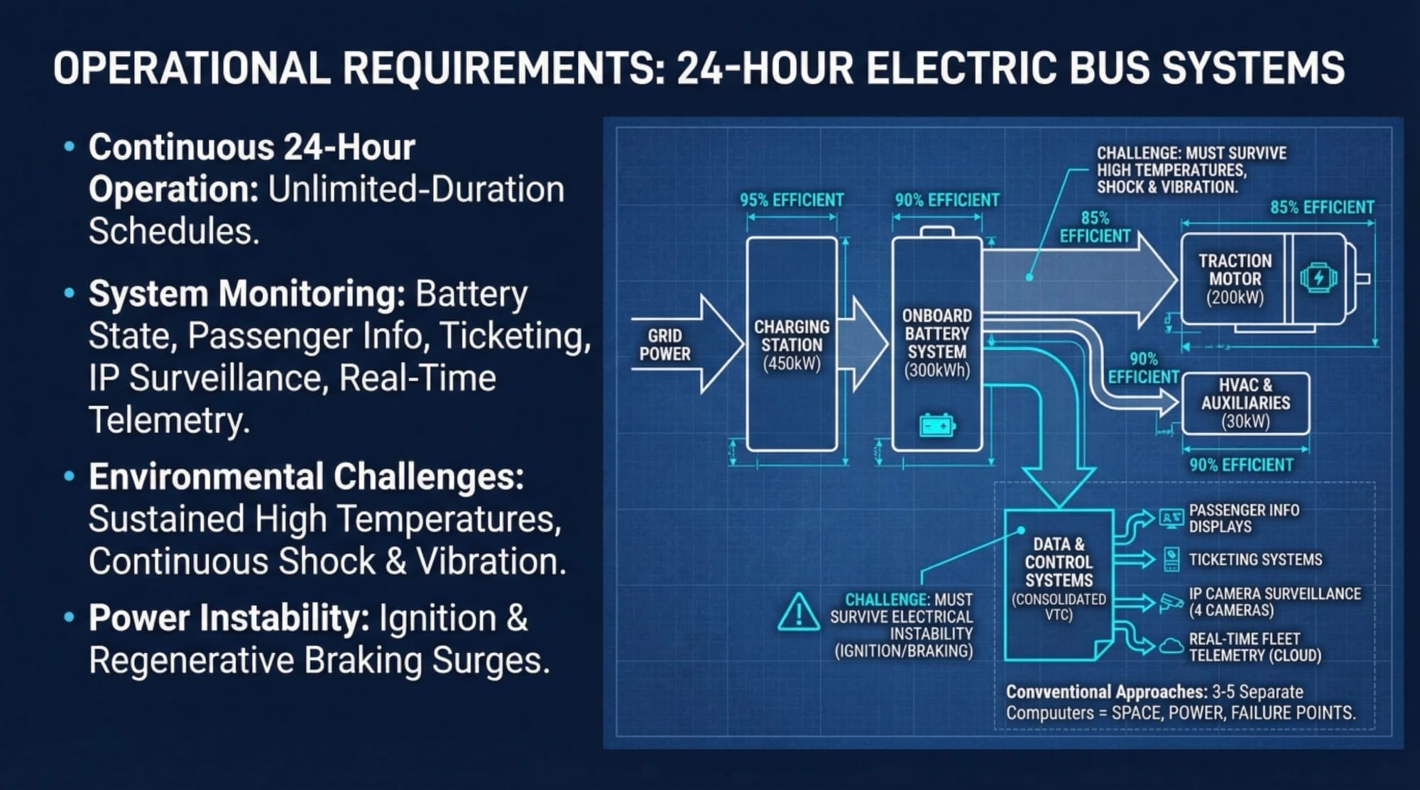
Objective: European electric bus manufacturers operate unlimited-duration schedules requiring continuous battery state monitoring, passenger information displays, ticketing integration, IP camera surveillance, and real-time fleet telemetry across 24-hour operational cycles. The conventional integration approach deploys three to five separate computers for these functions, each consuming installation space, drawing electrical power, and introducing discrete failure points.
The onboard computing infrastructure must simultaneously survive sustained high-temperature exposure in confined equipment bays, continuous shock and vibration from road operations, and unstable vehicle electrical systems during ignition events and regenerative braking—all while coordinating real-time data flows between battery management systems, control centers, and passenger-facing subsystems.
Technical Failures in Multi-Computer Electric Bus Deployments
1. Thermal Accumulation in Confined Mounting Compartments
Standard commercial computers generate 40-60W of heat per unit. When system integrators deploy three to five separate computers in adjacent mounting locations within confined bus equipment bays with limited airflow, cumulative thermal output reaches 150-300W in spaces typically measuring 40×30×20cm.
The Failure: Heat accumulation in enclosed compartments causes ambient temperatures to rise 15-20°C above external conditions. During summer operations where external temperatures reach 35°C, internal mounting bay temperatures climb to 50-55°C. Commercial-grade processors begin thermal throttling at 85°C junction temperature—with only 30-35°C thermal headroom from mounting bay ambient to processor junction, standard systems experience performance degradation within 90 minutes of continuous operation. Extended high-temperature exposure accelerates capacitor aging, reducing MTBF from rated 100,000 hours to observed 15,000-20,000 hours.
The Architectural Fix: Wide-Temperature Fanless Design
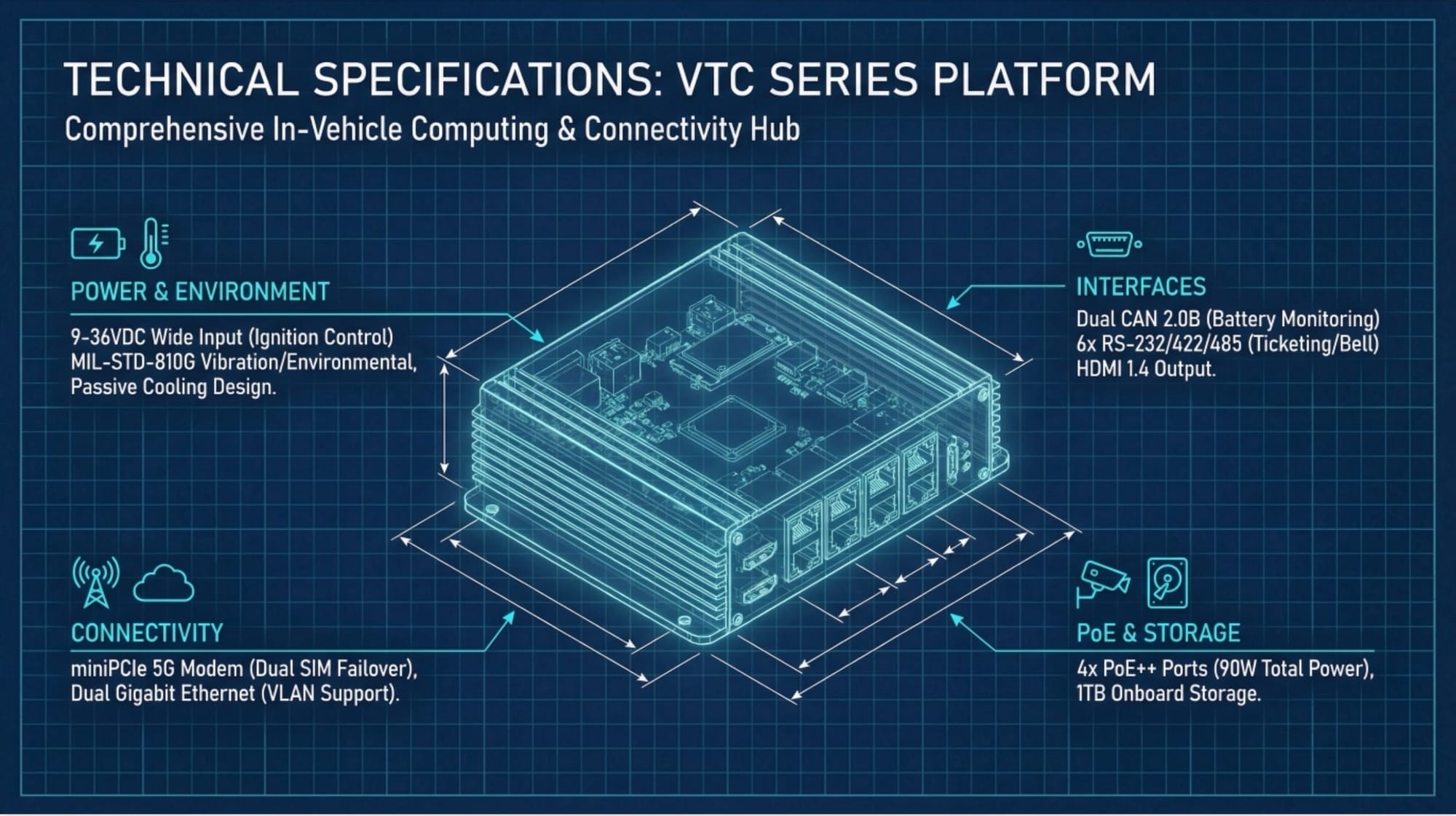
The VTC series eliminates active cooling through aluminum chassis heat-pipe architecture conducting processor heat across 450cm² of external surface area. Heat pipes transfer thermal energy from CPU directly to chassis walls with 0.15°C/W thermal resistance, enabling sustained operation from -40°C to 70°C with zero thermal throttling. Single-unit deployment eliminates 200-250W of cumulative heat generation from multi-computer configurations.
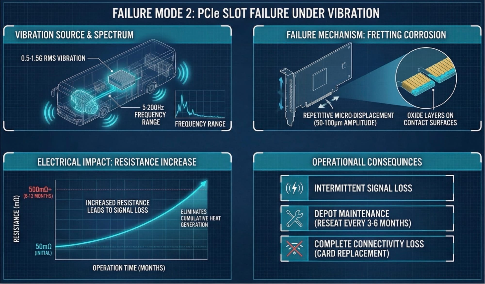
2. PCIe Slot Failure Under Continuous Vibration Exposure
Electric buses generate 0.5-1.5G RMS vibration across 5-200Hz frequency range during normal city operations—acceleration/deceleration events, expansion joint impacts, and pothole traversal create high-frequency shock impulses. Wireless communication modules, GPS cards, and CAN interface cards mounted in standard PCIe slots experience fretting corrosion at gold-plated edge connector contacts under these conditions. Related: urban transit computing. Related: vehicle height detection.
The Failure: Repetitive micro-displacement of PCIe card edge connectors against motherboard slots (50-100 micron amplitude) creates oxide layers on contact surfaces through electrochemical reaction. Contact resistance increases from initial 50mΩ to 500mΩ+ over 6-12 months of continuous operation. Communication cards experience intermittent signal loss during vibration events, requiring depot maintenance to reseat cards every 3-6 months. Severe cases result in complete connectivity loss requiring card replacement.
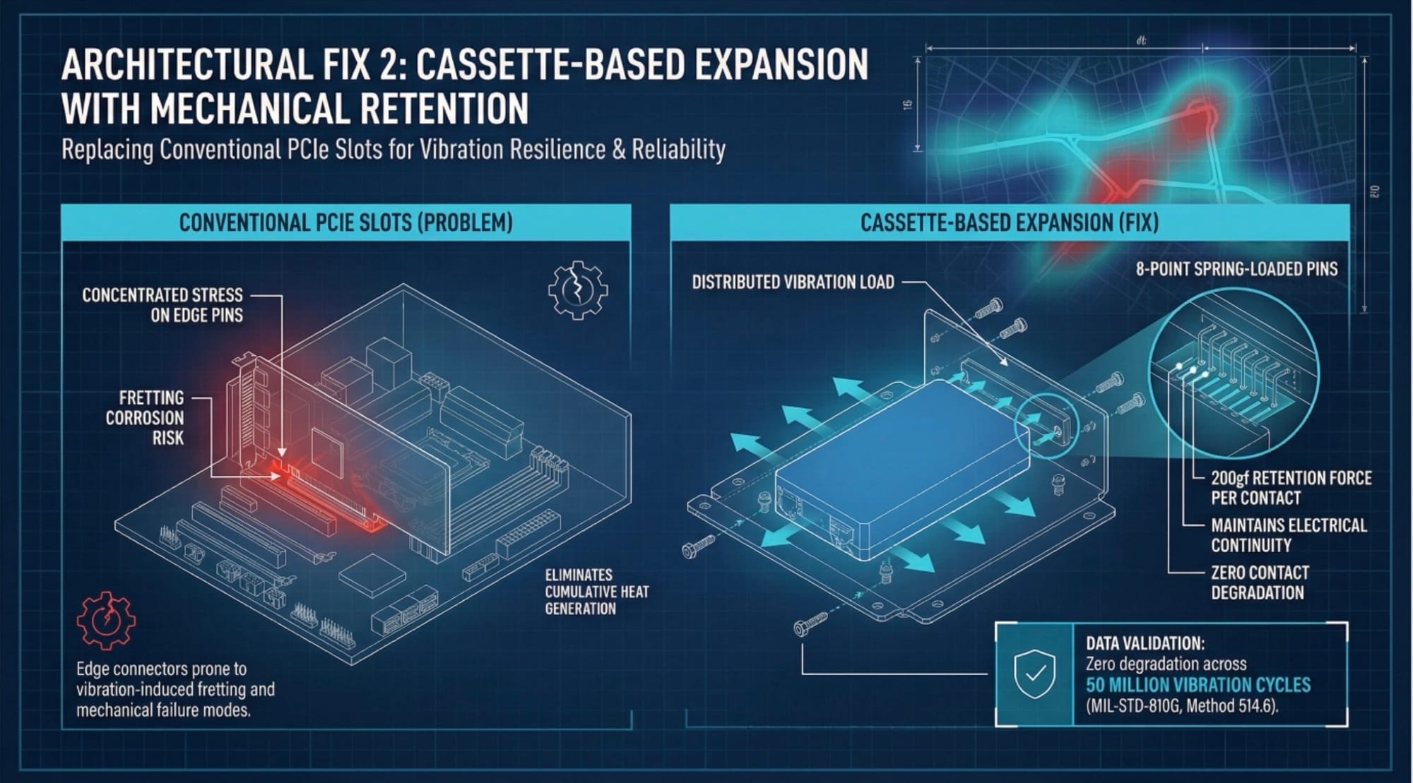
The Architectural Fix: Cassette-Based Expansion with Mechanical Retention
VTC series replaces conventional PCIe slots with Cassette module interfaces featuring bolted mechanical retention. Expansion modules mount through screw-fastened chassis brackets that distribute vibration loads across entire module footprint rather than concentrating stress on edge connector pins. Contact interface employs 8-point spring-loaded pins with 200gf retention force per contact, maintaining electrical continuity under sustained vibration. Zero contact degradation measured across 50 million vibration cycles per MIL-STD-810G Method 514.6 specifications.
3. Power Distribution Complexity and Startup Inrush Current
Deploying separate computers for battery monitoring, passenger systems, and fleet connectivity requires individual power supplies, each drawing 8-12A startup inrush current from the vehicle 24V bus during ignition events.
The Failure: Five separate computers create cumulative 40-60A inrush during simultaneous startup. Vehicle electrical systems experience voltage sag to 18-20V for 200-500ms, triggering undervoltage lockout circuits and causing random initialization failures requiring manual depot reset.
The Architectural Fix: Consolidated Power Architecture
VTC series integrates eight-channel I/O, dual Gigabit Ethernet with PoE++, HDMI output, CAN bus interface, and six COM ports within single 9-36V wide-input supply drawing 4A inrush versus 40-60A multi-computer baseline. Integrated ignition power control delays startup 2 seconds after detecting ignition signal, allowing vehicle electrical system stabilization.
Electric Bus Monitoring: Subsystem Consolidation Performance
Related reading: Nuvo-10108GC Cuts Water Treatment Alarm Response 68% with Edge AI.
| Metric | Multi-Computer Deployment | VTC Series Consolidated |
|---|---|---|
| Installation Footprint | 2,800cm³ (5 units) | 485cm³ (single unit) |
| Power Consumption | 185W continuous | 35W continuous (81% reduction) |
| Startup Inrush Current | 45-60A @ 24VDC | 4A @ 24VDC |
| Temperature Range | 0°C to 50°C typical | -40°C to 70°C certified |
| Vibration Resistance | Commercial grade | MIL-STD-810G (3Grms) |
| Cabling Infrastructure | 18 power + 22 signal cables | 1 power + 8 signal cables |
Integrated Capabilities: Dual CAN 2.0B channels for battery monitoring, four PoE++ ports (90W total) for IP cameras with onboard 1TB storage, six RS-232/422/485 ports for ticketing/bell systems, dual Gigabit Ethernet with VLAN support, miniPCIe 5G modem with dual SIM failover, HDMI 1.4 output for passenger displays.
Implementation Considerations
| Engineering Advantage | Implementation Trade-off |
|---|---|
| Consolidated Architecture: Single power feed eliminates five separate supplies, reduces harness weight by 4.2kg per vehicle, cuts installation time 41% | Single Point of Failure: Complete subsystem shutdown on computer failure. Requires 2-3 spare units per 50-vehicle fleet |
| Fanless Operation: Zero filter maintenance, no dust ingress failures. -40°C to 70°C rating supports arctic to desert climates | Limited GPU Options: Cassette expansion supports low-profile modules only. High-performance inference requires alternative platforms |
| Vibration Resistance: MIL-STD-810G certification reduces unscheduled maintenance 40% versus commercial computers | Premium Cost: Rugged components increase unit cost 40-60%. ROI through reduced cabling labor and eliminated subsystem computers |
Real-World Performance
European electric bus fleet (120 vehicles) achieved:
- Installation time: 6.5 hours per vehicle vs. 11 hours baseline (41% improvement)
- MTBF: 48,000 hours vs. 18,000 hours commercial-grade deployment
- Maintenance: Zero unscheduled service calls across 18 months (previous: 0.8 calls per vehicle-year)
Related Products
POC-551VTC: Compact fanless in-vehicle computer for smaller electric shuttles with 40% smaller footprint (1.8L). Features identical CAN bus and ignition control as VTC series with 8-35VDC input and conformal coating.
PB-9250J-SA Power Backup: Supercapacitor UPS providing 9,250Ws backup energy for controlled shutdown during vehicle electrical faults. Critical for third-rail gaps in hybrid electric/trolleybus deployments.
Contact Us
For technical specifications, product selection assistance, or electric bus integration engineering support, contact our engineering team at [email protected]. Our engineers can help you choose the right VTC series platform for your specific fleet monitoring requirements.
Visit www.neteon.net for detailed datasheets and technical documentation on rugged in-vehicle computing solutions.
FAQs
What temperature range does the VTC series support for electric bus deployments?
The VTC series operates from -40°C to 70°C using heat-pipe thermal architecture conducting processor heat across 450cm² of external surface area. This eliminates thermal throttling in confined equipment bays where multi-computer setups push ambient temperatures to 50–55°C during summer operations.
How does the VTC series handle vibration on electric bus routes?
The VTC series replaces standard PCIe slots with cassette module interfaces featuring bolted mechanical retention and 8-point spring-loaded pins at 200gf per contact. This eliminates fretting corrosion that degrades standard PCIe connections within 6–12 months of continuous bus operation under 0.5–1.5G RMS vibration.
What I/O connectivity does the VTC series provide for electric bus monitoring?
The VTC series integrates dual CAN 2.0B for battery monitoring, four PoE++ ports (90W total) for IP cameras with 1TB onboard storage, six RS-232/422/485 for ticketing and bell systems, dual Gigabit Ethernet with VLAN, miniPCIe 5G with dual SIM failover, and HDMI 1.4 for passenger displays — all in a single 485cm³ unit.
How much power does the VTC series save compared to multi-computer bus deployments?
The VTC series draws 35W continuous versus 185W for a typical 5-computer deployment — an 81% reduction. Single 9–36V wide-input supply draws 4A inrush versus 40–60A cumulative startup current, eliminating voltage sag issues that cause random initialization failures.
What real-world fleet results have been achieved with the VTC series?
A European electric bus fleet of 120 vehicles achieved 41% faster installation (6.5 vs 11 hours per vehicle), MTBF improvement from 18,000 to 48,000 hours, and zero unscheduled service calls across 18 months compared to 0.8 calls per vehicle-year with the previous multi-computer setup.