
TLDR
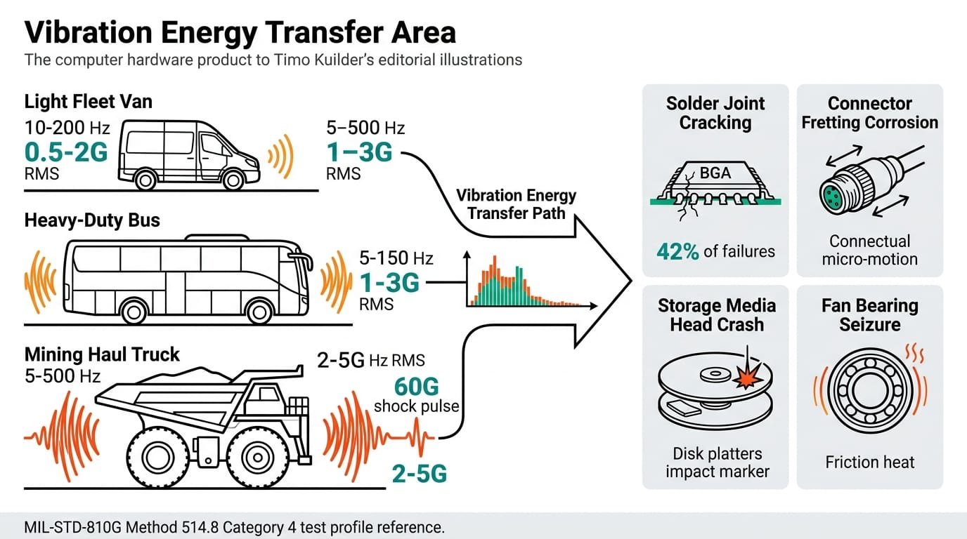
Vehicle-mounted edge computers face sustained random vibration from 5 Hz to 500 Hz, shock pulses exceeding 50 G, and thermal cycling that accelerates solder fatigue. This guide covers system architecture selection, vibration isolation strategies, connector hardening, and validation testing for fleet vehicles and mining haul trucks — using fanless, solid-state platforms rated to MIL-STD-810G Method 514.8.
Power is the other half of a vehicle install. See our companion vehicle edge AI power design guide on wide-range DC and ignition control.
Overview
Edge computing hardware installed in commercial vehicles, mining equipment, and construction machinery operates in one of the harshest vibration environments outside aerospace. Engine firing frequencies, road-surface excitation, and hydraulic system harmonics combine to produce complex multi-axis vibration profiles that destroy conventional IT hardware within months.
The electrical side — E-Mark, ISO 7637-2, and power-sequencing requirements — is covered in our automaker edge AI outlook for 2026–2030.
The failure modes are predictable: solder joint cracking on BGA packages, connector fretting corrosion from micro-motion, storage media head crashes, and fan bearing seizure. Each failure shares a root cause — mechanical energy coupling from the vehicle chassis into electronic assemblies that were never designed for continuous dynamic loading.
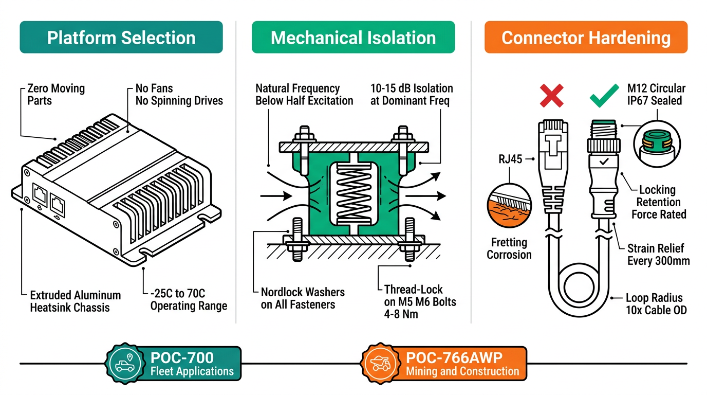
Designing a reliable vehicle-mounted computing platform requires addressing vibration at three levels: platform selection (eliminating moving parts), mechanical isolation (decoupling the chassis vibration path), and connector strategy (maintaining signal integrity under motion). Field data from fleet deployments confirms that purpose-built fanless systems reduce vibration-related failures by over 90% compared to commercial-grade alternatives.
System Architecture for Vehicle Environments
Selecting the right compute platform starts with matching the mechanical design to the vehicle's vibration signature. The table below maps common vehicle classes to their dominant excitation profiles and recommended platform architectures.
| Vehicle Class | Dominant Vibration Range | Peak Shock (G) | Recommended Platform | Key Design Feature |
|---|---|---|---|---|
| Light commercial (vans, trucks) | 10–200 Hz, 0.5–2 G RMS | 15–30 G | POC-700 | 0.57L fanless, lug-mount, -25°C to 70°C |
| Heavy-duty fleet (buses, long-haul) | 5–150 Hz, 1–3 G RMS | 20–40 G | POC-700 | MIL-STD-810G vibration, ignition power management |
| Mining haul trucks | 5–500 Hz, 2–5 G RMS | 30–60 G | POC-766AWP | IP67 sealed, M12 connectors, wide-temp -40°C to 70°C |
| Construction equipment | 8–300 Hz, 1.5–4 G RMS | 25–50 G | POC-766AWP | Waterproof, vibration-isolated internal mounts |
Both platforms share a critical architectural advantage: zero moving parts. No fans, no spinning drives, no mechanical relays. The POC-700 uses an extruded aluminum unibody as both chassis and heatsink, while the POC-766AWP adds a fully sealed IP67 enclosure with pressure-equalization vent for altitude and temperature swings.
Environmental Design Factors
Beyond platform selection, the mounting system and cable management determine whether vibration energy reaches sensitive components. The following parameters guide installation design.
| Design Factor | Parameter | Light Fleet Target | Mining/Construction Target |
|---|---|---|---|
| Mounting isolation | Natural frequency | >2× vehicle dominant freq | >2× dominant freq, rubber isolators |
| Fastener torque | M5/M6 bolts | 4–6 N·m with thread-lock | 6–8 N·m with Nordlock washers |
| Cable strain relief | Loop radius | >10× cable OD | >10× OD, strain-relief clamps every 300 mm |
| Connector type | Standard | DB9/RJ45 with locking clips | M12 circular, IP67 rated |
| Storage media | Type | NVMe M.2 (soldered or clipped) | NVMe M.2, no 2.5″ spinning drives |
| Power input | Voltage range | 8–35 VDC (ignition-safe) | 8–48 VDC, transient suppression to 80 V |
| Thermal margin | Max ambient | 60°C continuous | 70°C continuous, -40°C cold start |
The single most common installation mistake is rigid-mounting a compute platform directly to the vehicle frame. Without isolation, every chassis resonance transfers directly into the PCB assembly. Even MIL-STD-rated hardware benefits from 10–15 dB of isolation at the dominant excitation frequency. Use elastomeric mounts with a natural frequency below half the lowest excitation frequency of concern.
Integration Notes
Power conditioning is the second most frequent failure source after vibration. Vehicle electrical systems produce load-dump transients up to 80 V (24 V systems) or 120 V (heavy equipment with alternator overshoot). Both the POC-700 and POC-766AWP accept wide-range DC input with built-in transient suppression, but external TVS diodes rated for the specific vehicle's alternator profile add a margin of safety for mining environments.
Ignition management matters for fleet vehicles that cycle power frequently. The POC-700 supports configurable ignition-on/off delay, allowing the system to complete data writes and gracefully shut down before power is removed — preventing filesystem corruption that plagues systems connected directly to ignition-switched circuits.
Connector hardening for mining and construction requires replacing every RJ45 and USB-A connection with M12 or equivalent sealed circular connectors. The POC-766AWP provides M12 Ethernet and waterproof I/O natively, eliminating the adapter cables that introduce additional failure points.
Validation Checklist
Before deploying vehicle-mounted edge computers, validate these items against the target vehicle's measured vibration profile:
- Random vibration testing per MIL-STD-810G Method 514.8, Category 4 (ground vehicle) — minimum 1 hour per axis
- Mechanical shock per MIL-STD-810G Method 516.8 — 40 G, 11 ms half-sine, 3 shocks per axis
- Thermal cycling -40°C to +70°C, 10 cycles minimum, with vibration applied simultaneously
- Power transient immunity per ISO 7637-2 (12 V systems) or ISO 7637-3 (24 V systems)
- Connector retention force after 500 mating cycles plus 4 hours random vibration
- Storage integrity: 10,000 power-cycle test with filesystem verification after each cycle
- EMC per CISPR 25 Class 5 for vehicles with sensitive radio equipment
For the wider rolling-stock standards picture that sits alongside vibration testing, see our EN 50155 compliance guide for railway edge AI.
Conclusion
Vehicle-mounted edge computing reliability depends on three design decisions made before the first unit ships: selecting a fanless, solid-state platform rated for the target vibration envelope; isolating that platform from chassis resonances with properly tuned mounts; and specifying sealed connectors with adequate retention force. The POC-700 addresses light-to-heavy fleet applications in a 0.57-liter form factor, while the POC-766AWP extends that reliability envelope to IP67-sealed mining and construction environments. Contact [email protected] for vibration test reports and mounting templates, or visit www.neteon.net for full product datasheets.
Related: Edge AI Computer Buyer's Guide for Railway & Transit Applications
FAQs
What vibration levels do vehicle-mounted computers need to withstand?
Light commercial vehicles produce 0.5-2 G RMS at 10-200 Hz, while mining haul trucks generate 2-5 G RMS across 5-500 Hz with shock pulses up to 60 G. Edge computers must be rated per MIL-STD-810G Method 514.8 Category 4 for ground vehicle applications.
Why are fanless computers better for vehicle installations?
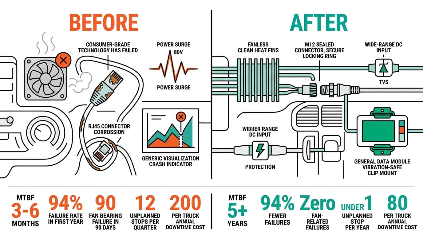
Fan bearings are the first mechanical component to fail under sustained vibration. Fanless designs like the POC-700 and POC-766AWP eliminate all moving parts — no fans, no spinning drives, no mechanical relays — removing the most common vibration failure modes entirely.
How should vehicle-mounted PCs be mounted to reduce vibration damage?
Use elastomeric isolation mounts with a natural frequency below half the vehicle's lowest excitation frequency. Never rigid-mount directly to the chassis frame. Even MIL-STD-rated hardware benefits from 10-15 dB of vibration isolation at the dominant frequency.
What connectors survive harsh vehicle vibration environments?
Standard RJ45 and USB-A connectors fail from fretting corrosion under vibration. Use M12 circular connectors with IP67 sealing for mining and construction. The POC-766AWP provides M12 Ethernet natively. For fleet vehicles, use locking-clip DB9 and latched RJ45 connections.
What power protection is needed for vehicle-mounted edge computers?
Vehicle electrical systems produce load-dump transients up to 80V (24V systems) or 120V (heavy equipment). Select platforms with wide-range DC input (8-48 VDC) and built-in transient suppression. Add external TVS diodes rated for your specific alternator profile and test per ISO 7637-2/3.
For a related in-vehicle deployment, see how an NRU-220 cut open-pit haul-truck near-miss events 71%.