

TLDR
An edge AI system is four layers working together: sensors that capture the physical world, an edge computer that runs inference on that data, an orchestration layer that keeps models and containers current, and a connectivity path that moves results to the cloud. Most failed deployments are not model problems. They are architecture problems, usually a mismatch between the compute you picked and the environment, bandwidth, or update cadence the site actually demands. This guide walks the full path from sensor to cloud, shows where each decision gets made, and points to the deeper build guides for every layer.
Overview
Teams tend to start an edge AI project at the model. They train a detector, hit good accuracy on a laptop, and then discover the hard part was never the model. It was everything around it: getting clean frames off a camera on a moving vehicle, fitting the inference workload onto hardware that survives a substation summer, pushing a model update to 300 sites without sending a technician to each one, and doing all of it inside a bandwidth budget that a cellular link can honor.
That surrounding structure is the system. Getting it right is a design exercise, not a coding one. This pillar lays out the reference architecture we use across every deployment Neteon supports, from a single roadside camera to a fleet of autonomous mobile robots. Each section links to a focused build guide so you can go a level deeper wherever your project needs it.
If you have not settled on hardware yet, start with our companion guide on choosing an industrial edge AI computer, which covers chassis, thermal design, and CPU versus GPU selection in detail. For the environmental and certification side, the industrial ruggedness and compliance reference explains which ratings a given site demands. And because every layer here talks over an industrial network, the protocols and connectivity reference is the map for the wire between the boxes.
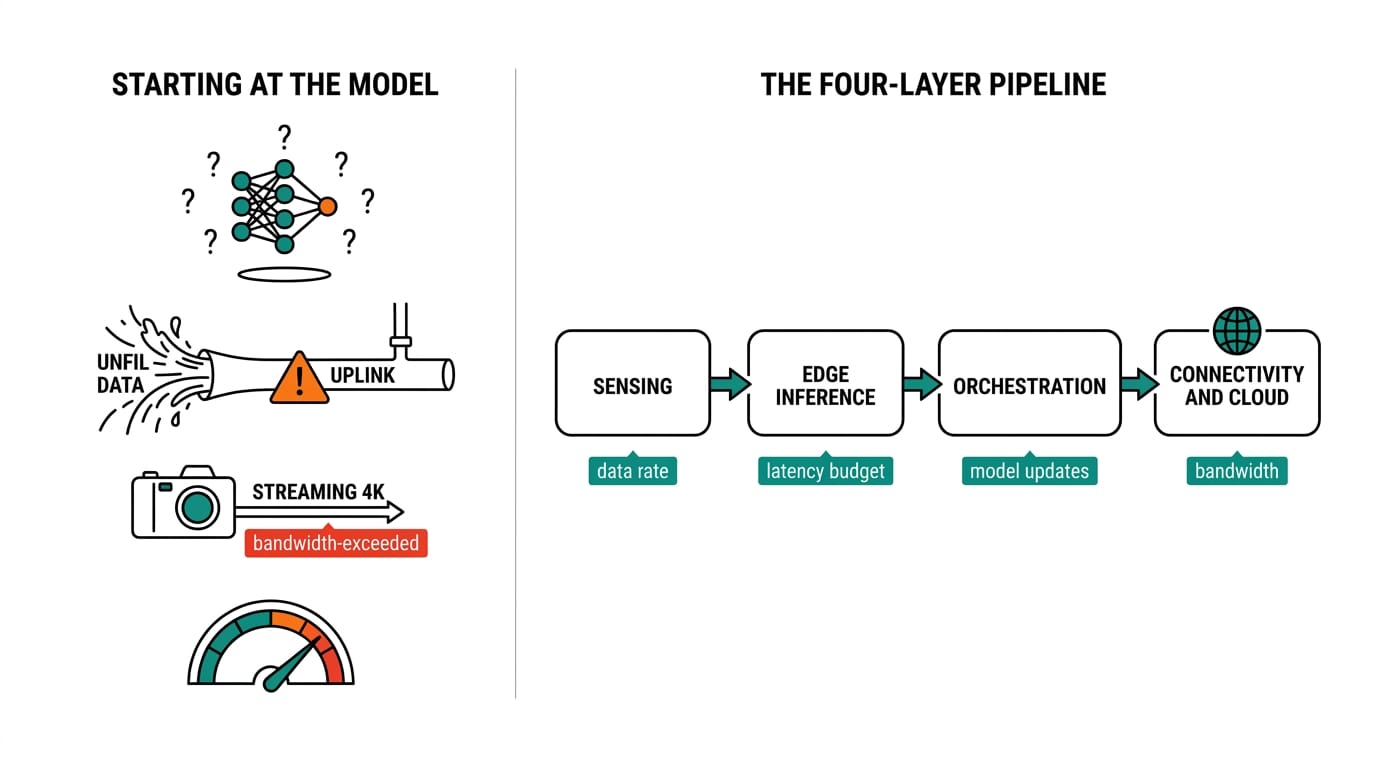
The four layers of an edge AI system
Think of the system as a pipeline with four stages. Data enters at the left as raw physical signal and leaves at the right as a decision, a dashboard row, or a cloud record. Each stage has its own failure modes and its own design questions.
| Layer | What it does | Typical hardware | Main design question |
|---|---|---|---|
| 1. Sensing and ingestion | Captures frames, waveforms, or telemetry | Cameras, lidar, PLCs, vibration and current sensors | How much raw data, and over which interface? |
| 2. Edge inference | Runs the model close to the source | Fanless industrial PC, GPU or NPU compute | Does the workload fit the thermal and power envelope? |
| 3. Orchestration and lifecycle | Deploys, monitors, and updates models and containers | Same edge node, plus a fleet controller | How do updates reach the field without a truck roll? |
| 4. Connectivity and cloud | Moves results upstream, pulls config down | Cellular or wired gateway, MQTT broker, cloud backend | What has to leave the site, and how often? |
The value of drawing it this way is that it separates decisions that people usually tangle together. Camera resolution is a Layer 1 question. Whether you need an RTX GPU is a Layer 2 question. They interact, but you solve them in order, because the answer at Layer 1 sets the load that Layer 2 has to carry.
Layer 1: Sensing and data ingestion
Everything downstream inherits the choices made here. A 4K camera at 30 frames per second produces roughly an order of magnitude more pixels per second than a 1080p feed, and that difference lands squarely on the inference hardware. So the first design act is honest sizing: how many sensors, at what resolution and rate, over which physical interface.
The interface matters as much as the data rate. Machine vision cameras commonly use GigE Vision or USB3 Vision, each with its own cabling limits and CPU cost for framegrabbing. Industrial sensors and controllers speak Modbus, EtherCAT, PROFINET, or CAN bus depending on the vintage and vendor of the plant. An edge node has to physically terminate all of that, which is why port count and isolation are selection criteria, not afterthoughts. A compact fanless unit like the POC-700 exists precisely for the ingestion role: it sits near the sensors, terminates serial and CAN and GigE, and hands clean data to a heavier compute node or handles a light model itself.
Two ingestion patterns cover most deployments. In the first, the edge node grabs frames directly and runs inference in the same box, which is the norm for vision. In the second, a field gateway aggregates many low-rate sensors, normalizes their protocols, and forwards a tidy stream. Our walkthrough on connecting a cellular IoT gateway to a Neousys POC-700 shows the second pattern end to end for a moving fleet, and the remote monitoring stack build shows how sensor data becomes an MQTT feed a broker can route.
One rule saves a lot of pain: filter at the edge, not in the cloud. If a vibration sensor reports 1,000 samples a second but only an anomaly matters, the ingestion layer should be where you decide what to keep. Sending everything upstream to sort out later is how bandwidth budgets get blown in week one.
Layer 2: Edge inference and compute selection
This is the layer people think of as the whole project, and it is where the hardware decision gets made. The question is narrow: does the inference workload fit inside the thermal, power, and physical envelope of the site? A model that runs at 60 frames per second on a bench GPU is worthless if the box that hosts that GPU cannot shed heat inside a sealed roadside cabinet at 55 degrees Celsius.
Three compute classes cover the field, and they are not interchangeable.
| Compute class | Best for | Representative product | Trade-off |
|---|---|---|---|
| CPU only | Light vision, sensor analytics, protocol work | POC-700, Nuvo-11000 | Lowest power and heat, limited model complexity |
| CPU plus discrete GPU | Multi-camera vision, high frame rates, large models | Nuvo-9160GC | Highest throughput, needs thermal and power headroom |
| Integrated AI accelerator | Efficient deep learning at modest power | NRU-220 | Great performance per watt, tied to a specific SDK |
A general-purpose expandable platform such as the Nuvo-11000 handles CPU-bound analytics and moderate inference while leaving PCIe room to grow. When a workload is genuinely GPU-bound, several high-rate camera streams or a heavy detector, the Nuvo-9160GC carries a discrete RTX-class card in a chassis built to cool it. For deep learning where power per watt is the constraint, the NRU-220 runs on an NVIDIA Jetson Orin module and delivers strong inference throughput at a fraction of the draw of a discrete GPU. Choosing between these is the core of our platform selection guide, and when the workload is specifically machine vision, the camera-to-GPU design guide walks the sizing math from sensor resolution back to required TOPS.
Thermal design is where edge inference projects most often fail quietly. A fanless enclosure trades peak sustained performance for reliability and sealing, and in most field sites that is the correct trade. Fans are moving parts, and moving parts are the first thing to die in dust, vibration, or salt air. The compliance side of this, ingress ratings, shock and vibration standards, wide-temperature operation, is covered in the ruggedness and compliance reference. Pick the environment rating before you pick the silicon, because a rating you cannot meet eliminates hardware options no matter how fast they are.
Latency, throughput, and the numbers that decide the design
Layer 2 lives or dies on two numbers: how many inferences per second the workload demands, and how long each one is allowed to take. Throughput is set by your sensors, the frame or sample rate multiplied by the number of streams. Latency is set by the job, the gap between a defect passing the camera and the reject arm having to move, or between a hazard appearing and a vehicle needing to brake. Size the compute to the tighter of the two, then leave headroom, because a node running at 95 percent has nothing left for a model update or a traffic spike.
| Workload | Rough latency budget | Practical compute floor |
|---|---|---|
| Line-speed visual inspection | 30 to 100 ms per frame | Discrete GPU (Nuvo-9160GC) |
| Condition monitoring, vibration or current | 100 ms to seconds | CPU analytics (Nuvo-11000) |
| Mobile robot or vehicle perception | Under 50 ms end to end | Efficient accelerator (NRU-220) |
| Protocol translation and telemetry | Seconds | Compact fanless node (POC-700) |
Two techniques buy back headroom when a model is close to the edge of the hardware. Quantizing a model to lower precision, from 32-bit to 8-bit integer where accuracy allows, can multiply throughput several times over on the same silicon. Batching frames trades a little latency for a lot of throughput when the job tolerates it. Both are model-side choices that change the hardware you need, which is the clearest reason to treat Layers 1 and 2 as one decision rather than two. The platform selection guide works through these trade-offs against real product specs.
Layer 3: Orchestration and model lifecycle
A model is not a product you ship once. It drifts. The lighting at a site changes with the seasons, a new defect type shows up, a camera gets nudged, and accuracy quietly erodes. The orchestration layer is what keeps a fielded system honest over the years it will actually run.
Two capabilities live here. The first is deployment and isolation: packaging the inference application so it runs the same on every node and can be replaced without disturbing the operating system underneath. Containers are the standard answer, and our guide on edge orchestration and container deployment on industrial PCs explains how that works on hardware that has no data-center luxuries. The second capability is the model lifecycle itself: how you retrain, validate, and roll out a new version, and how you roll back when the new version underperforms. That full loop is the subject of our AI model lifecycle guide.
The design pressure at this layer is scale. One node you can update by hand. Three hundred nodes across a region you cannot. Once a fleet passes a few dozen sites, over-the-air updates and remote monitoring stop being nice-to-have and become the only economical option, which is exactly the case our remote management of edge AI fleets guide is built around. The hardware implication is modest but real: the edge node needs enough storage endurance and memory headroom to hold two model versions and a working container set at once, so an update never leaves a site with no running model.
For any deployment where downtime carries a safety or revenue cost, orchestration also covers redundancy. Running a standby inference path, health-checking the primary, and failing over cleanly is a system property you design in, not a patch you add later. We cover the patterns in the high-availability edge AI design guide.
Layer 4: Connectivity and the cloud
The last layer answers a question that should have been asked at the very start: what actually has to leave the site? The whole point of edge AI is that most data never travels. Inference happens locally, and only the distilled output, an alert, a count, a status change, a periodic health record, moves upstream. Getting this boundary right is what makes a cellular-connected fleet affordable.
Connectivity comes in wired and wireless forms, and the choice is dictated by the site. A factory has Ethernet and often fiber. A wind turbine, a haul truck, or a roadside cabinet has cellular, sometimes private LTE or 5G, sometimes nothing but a metered SIM. That constraint flows all the way back to Layer 1, because a thin uplink forces aggressive edge filtering. The messaging pattern that fits this world is publish-subscribe: the edge node publishes compact messages to an MQTT broker, and cloud services subscribe to what they need. Our edge-to-cloud data pipeline guide traces a single reading from sensor through broker to dashboard, and the converged IT/OT network guide covers how the operational and information networks meet without collapsing the security boundary between them.
Security belongs here too, and it is not optional. The moment an edge node has a path to the cloud, it has an attack surface. Device identity, encrypted transport, and signed updates are baseline. Treat the connectivity layer as the place where the trust boundary is enforced, and design it against a recognized framework rather than inventing controls per site.
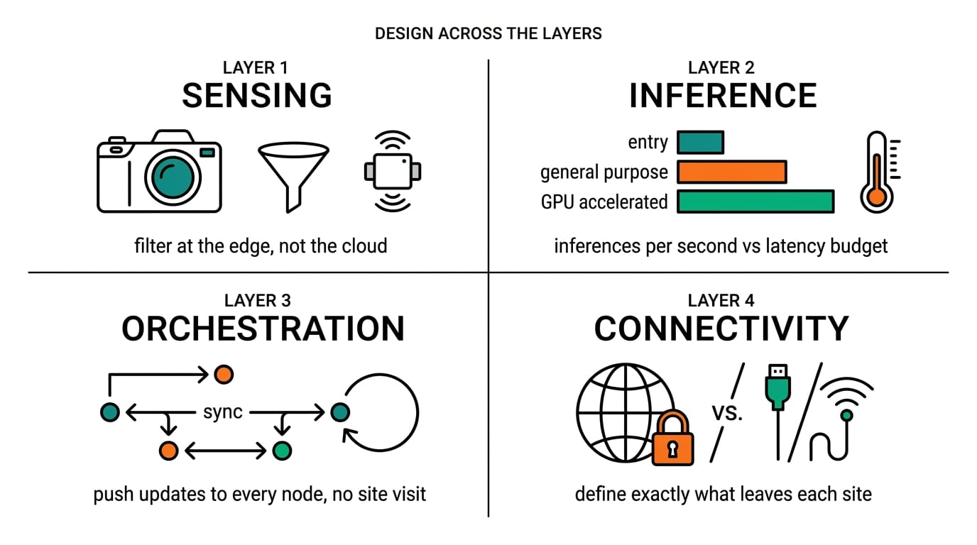
Designing across the layers: environment and compliance
The four layers are clean on a diagram, but a real site cuts across all of them at once. A deployment on a train has to satisfy railway shock, vibration, and power standards in Layer 2, tolerate an intermittent cellular link in Layer 4, and survive years of updates in Layer 3, all in the same box. Environmental and regulatory requirements are therefore not a separate step. They are a filter you apply to every layer.
| Environmental factor | Layer most affected | Design response |
|---|---|---|
| Wide temperature range | 2 (inference) | Fanless chassis, wide-temp components, thermal headroom |
| Shock and vibration | 1 and 2 | Solid-state storage, ruggedized connectors, no spinning media |
| Ingress (dust, water) | 1 and 2 | Sealed enclosure, appropriate IP rating |
| Limited or metered uplink | 1 and 4 | Edge filtering, store-and-forward, compact messaging |
| Unattended sites | 3 | Remote management, over-the-air updates, watchdog and recovery |
The point of the table is that a single site constraint ripples. A metered cellular link is not just a Layer 4 concern; it dictates how much filtering Layer 1 must do. Unattended operation is not just a Layer 3 concern; it decides whether you can ever afford to send someone to reboot a hung box. Designing the layers in isolation is how a system passes the bench and fails the field.
A worked reference architecture
To make this concrete, here is a representative build for a common case: multi-camera visual inspection on a production line, with results and health telemetry sent to a plant dashboard.
| Layer | Component | Role in this build |
|---|---|---|
| 1. Ingestion | Two to four GigE Vision cameras | Capture the inspection zone at line speed |
| 2. Inference | Nuvo-9160GC with an RTX-class GPU | Run the defect detector across all camera streams |
| 3. Orchestration | Containerized inference app plus a fleet controller | Deploy the model, monitor accuracy, push updates |
| 4. Connectivity | Wired Ethernet to an MQTT broker on the plant network | Publish pass/fail results and node health to the dashboard |
Swap the components and the same skeleton serves a very different job. Replace the cameras with vibration and current sensors, drop the compute to a Nuvo-11000 because the workload is analytics rather than heavy vision, and move the uplink to a cellular gateway, and you have a condition-monitoring node for a remote pump or turbine. Replace the compute with an NRU-220 and the same architecture becomes a power-efficient perception node for a mobile robot. The layers do not change. Only the parts that fill them do, which is the whole reason to design at the layer level first.
Validation checklist
Before a design leaves the whiteboard, walk it against these questions. Each maps to a layer and to a deeper guide.
First, sizing. Have you calculated the real data rate at Layer 1, in pixels or samples per second, and confirmed Layer 2 can process it at the required latency? A model that keeps up in a demo but falls behind at full line speed is a sizing miss.
Second, environment. Does the chosen chassis meet the site's temperature, ingress, shock, and vibration requirements, verified against the actual standard rather than a marketing summary? The ruggedness reference is the checklist for this.
Third, updates. Can you push a new model to every node without a site visit, and roll it back if accuracy drops? If the answer involves a technician and a USB stick, the fleet management design is not finished.
Fourth, bandwidth. Have you defined exactly what leaves each site, and confirmed it fits the uplink on its worst day? The edge-to-cloud pipeline guide shows how to keep that footprint small.
Fifth, failure. When a node hangs, a link drops, or a model misbehaves, what happens? If the honest answer is that the line stops or the safety function goes dark, revisit the high-availability design before you build.
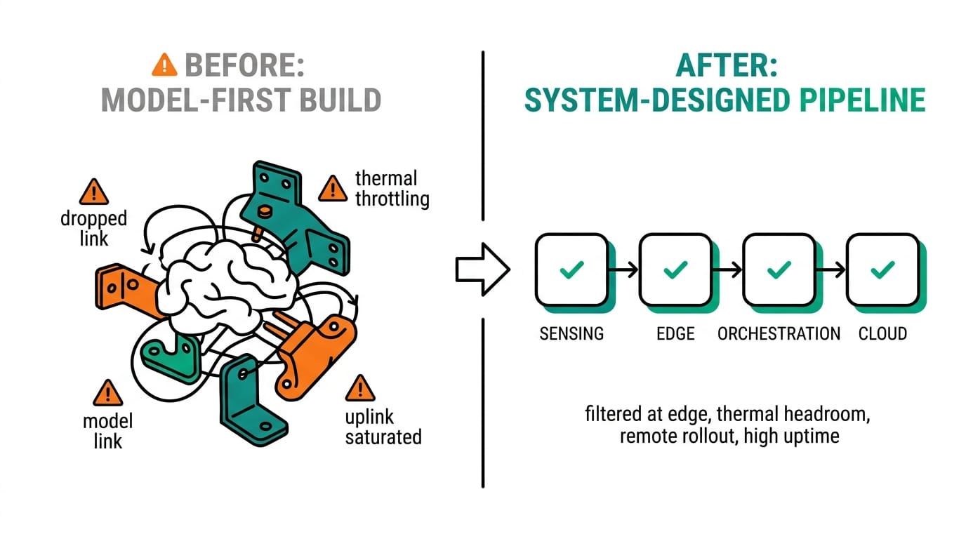
Conclusion
An edge AI system is not a model with some hardware attached. It is four layers, sensing, inference, orchestration, and connectivity, each with its own design questions, and it works only when the choices made at one layer respect the constraints of the others. Start at the environment and the data, size the compute to fit, plan the update path before the first node ships, and keep the cloud footprint to the minimum the job requires. Do that and the model, when it drifts, is a thing you can fix from your desk rather than a truck roll to a mountaintop.
Follow Neteon on LinkedIn for more deep dives on edge AI architecture, or reach us at [email protected] or www.neteon.net to talk through a sensor-to-cloud design for your site.
Related Products


FAQs
What are the four layers of an edge AI system?
Sensing and ingestion (cameras and sensors that capture data), edge inference (the industrial computer that runs the model locally), orchestration and lifecycle (how models and containers get deployed, monitored, and updated), and connectivity and cloud (moving distilled results upstream). Each layer has its own design questions, and the choices at one layer constrain the others.
Do I need a GPU for edge AI, or is a CPU enough?
It depends on the workload. Light vision, sensor analytics, and protocol translation run well on CPU-only nodes like the POC-700 or Nuvo-11000. Multi-camera vision at high frame rates needs a discrete GPU such as the Nuvo-9160GC. Deep learning where power efficiency matters is best served by an integrated accelerator like the NRU-220 on NVIDIA Jetson Orin. Size the compute to your latency and throughput budget, then leave headroom.
How much data should an edge AI system send to the cloud?
As little as possible. The point of edge AI is that inference happens locally and only the distilled output, an alert, a count, a status change, or a periodic health record, travels upstream. Filtering at the edge rather than in the cloud is what keeps a cellular-connected deployment affordable and keeps the system inside its bandwidth budget on a bad day.
How do you update models across a large fleet of edge devices?
Through over-the-air updates and remote monitoring. Once a fleet passes a few dozen sites, sending a technician to each node is not economical, so the orchestration layer packages inference apps in containers, monitors accuracy, pushes new model versions remotely, and rolls back when a version underperforms. The edge node needs enough storage and memory headroom to hold two model versions at once so an update never leaves a site without a running model.
Why do edge AI deployments fail in the field after working on the bench?
Almost always because of an architecture mismatch rather than a model problem. Common causes are compute that cannot shed heat inside a sealed enclosure, an uplink too thin for the data the site tries to send, no remote update path for unattended nodes, or no failover when a node hangs. Designing the four layers together, and applying environmental and compliance constraints to every layer, is what closes the gap between the bench and the field.